Methodology
The isometric SVG contains implicit 3D information. Polygon angles and edge lengths encode face orientation and cuboid dimensions, while shared edges and layer relationships help recover the relative depth of connected traits. Geometry that is fully occluded is completed using consistent rules for each trait family.
Each trait SVG stores numeric values for the position and size of its faces on the 2D plane. It also contains an affine transformation matrix for each face. The script applies that matrix to the four source corners to calculate their final 2D coordinates, which are stored as screen_points.
The angles of the transformed edges identify the corresponding X, Y, and Z directions in model space. Their lengths determine the cuboid dimensions, using 40 SVG units for one model unit. A 3D point (x, y, z) produces the 2D SVG position (sx, sy) through this projection. Here, S is the scale of 40 SVG units per model unit, and c is the isometric horizontal projection factor √3 / 2, equivalent to cos(30°).
c = √3 / 2
The same relationship is used in reverse during reconstruction. Once a source face is matched to a cuboid boundary, its numeric 2D coordinates are mapped onto the corresponding 3D face. Shared edges between connected traits are then used to resolve the remaining depth offset.
Resolving the missing depth
The SVG encodes cuboid dimensions and relative screen position, but the projection does not provide one unique 3D position. In the following equation, P is the projection matrix, p₀ is one valid 3D position, t is a scalar distance along the projection’s null direction, and p(t) is any other 3D position along that direction. Moving a point equally along all three model axes does not change its projected SVG position:
This is why a polygon cannot be placed from its screen position alone. The script compares shared edges between traits and tests where a child trait can attach to its parent. Matching edges across several faces supplies the missing depth.
The source polygon, face direction, parent trait, and recovered offset are kept with the geometry. This makes it possible to trace a model surface back to the SVG data used to create it.
Trait-specific geometry

Every Body is completed as the same five-row structure. Frog, Duck, Bot, Cow, and Hyena add reusable rules for geometry that differs from the standard form, including mouths, teeth, nostrils, heads, and ears.
Directional rules use the character’s left and right rather than screen-left and screen-right. This keeps asymmetric colors, pupils, ears, and chest patterns on the correct side of the model.
Recesses and projections
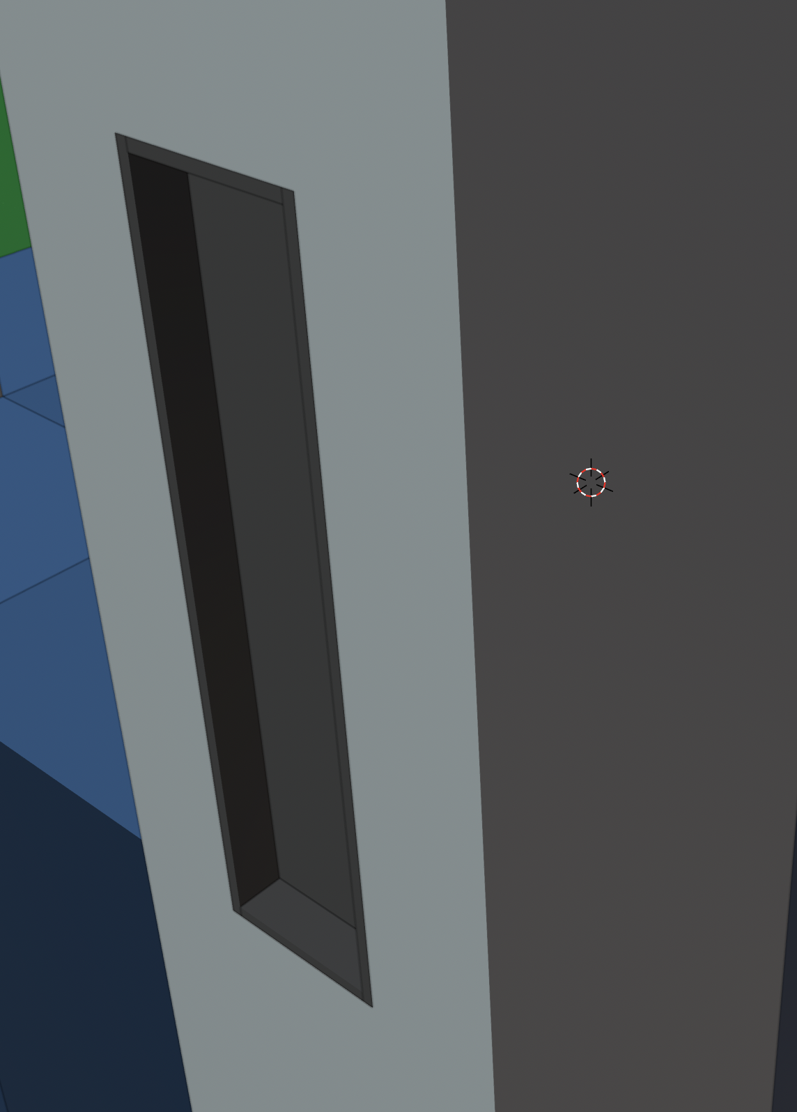
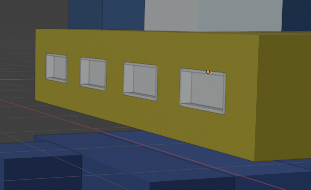
Small features are treated according to what they represent. Pupils, teeth, nostrils, and scanner openings are shallow recesses. The Imperial visor projects outward. In both cases the SVG supplies the position and outline; the trait rule supplies the depth.
Keeping the SVG colors
The SVG already uses separate colors for the top and side faces of each cuboid. Those hex values are assigned directly to the corresponding Blender faces.
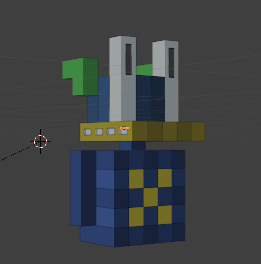
The comparison render uses emission materials so Blender does not add a second layer of lighting and change the source colors. Each model is rendered beside its SVG at a fixed isometric camera angle for review.
Blender uses linear color values, so each normalized SVG color channel is converted from sRGB before it is assigned to a material. In the following equation, CsRGB is the source channel value from 0 to 1, and Clinear is the corresponding linear value.
Clinear = CsRGB / 12.92if CsRGB ≤ 0.04045Clinear = ((CsRGB + 0.055) / 1.055) ** 2.4otherwise